§2.4 Boolean Logic
How do AND, OR, and NOT gates process binary inputs — and how do you trace a logic circuit through a truth table?
Boolean logic is the foundation of all digital electronics. Every decision a computer makes — whether an IF condition is true, whether a circuit should output a 1 — reduces to the three fundamental gates: AND (outputs 1 only when both inputs are 1), OR (outputs 1 when at least one input is 1), and NOT (inverts the input). These three gates can be combined into any logic circuit, and any logic circuit can be described by a truth table.
OCR requires AND, OR, and NOT only — XOR is not in the spec, which is a key contrast with AQA. Students must draw and read logic diagrams using the standard gate symbols, construct truth tables for simple and compound expressions (multiple gates in sequence or combination), and apply logic to solve a described real-world problem. The connection to programming is direct: every IF condition in code is a Boolean expression being evaluated by the CPU's logic gates.
Truth table templates
What students must understand
- AND gate: output is 1 ONLY when all inputs are 1
- OR gate: output is 1 when at least one input is 1
- NOT gate: output is the inverse of the input (1 becomes 0, 0 becomes 1)
- Logic diagrams: standard gate symbols; reading inputs to outputs through a circuit
- Truth table: lists every possible combination of inputs and the corresponding output(s)
- For n inputs: truth table has 2ⁿ rows (2 inputs → 4 rows, 3 inputs → 8 rows)
- Combining gates: trace from inputs through each gate in sequence, building up intermediate columns
- Applying Boolean operators to solve real problems (e.g. access control, sensor logic)
- Note: XOR is NOT required by OCR J277 — do not include it in exam answers unless explicitly shown in a question diagram
Diagrams
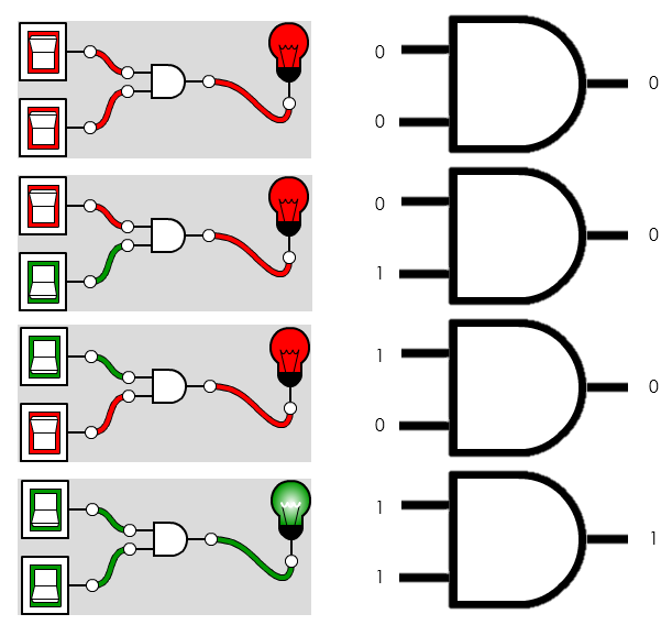
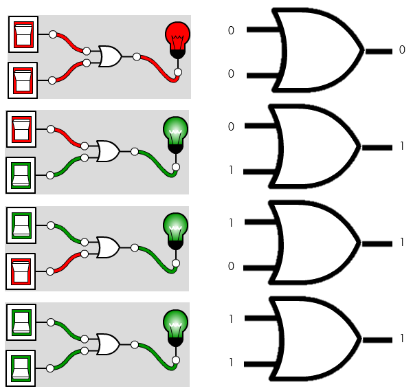
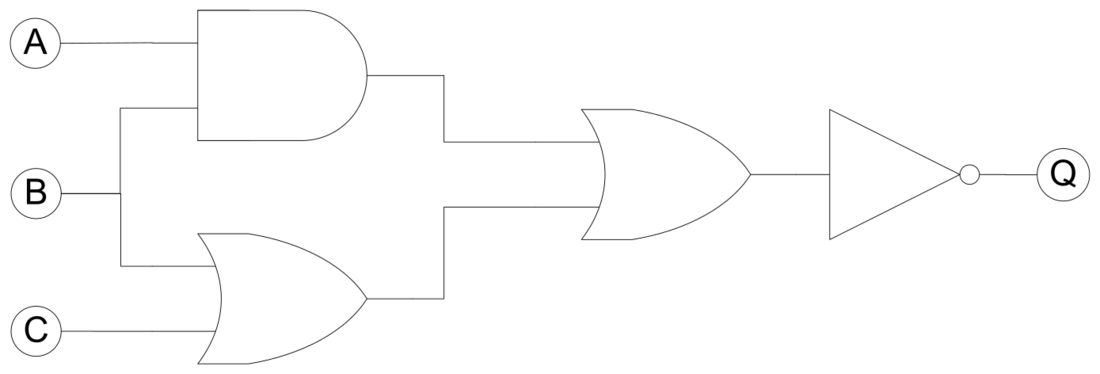
Diagrams: PG Online (Paul Long), OCR J277 textbook. Used under the school site licence.
Linking questions
- How do AND/OR/NOT connect to the boolean operators in programming? → §2.2 Programming Fundamentals
- How do logic gates relate to CPU operations? → §1.1 Systems Architecture (ALU)
Practice
- §2.4 Boolean Logic practice questions — 1 printable question set from the PG Online textbook pack